|
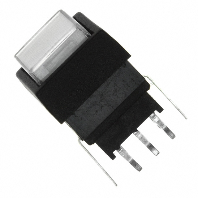
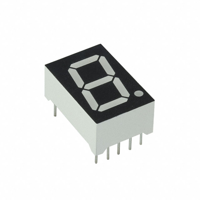
I have a project that I have been thinking of putting together for a while to have a quick visual assistant to count closed positions (due to repairs needed at the position) imputed by the operator. Right now we use a printed piece of paper laminated and a expo marker which over time causes the laminate to take on the marker color and looks cheap and out of place in my opinion. I want to preface that I'm a total noob when it comes to electronics but I have a small understanding of schematics and componants on them so please bare with me as I learn from you all. The project consists of five columns of light up latching switches and a single LED digit for each column and a double digit for total, of those five columns some have seven positions some have eight some have nine positions. But the entire project has a total of 40 positions. For each switch triggering a light to the on position the digit corresponding to the column decreases as well as the total digits decrease as well. I'm not really sure where to start as far as circuit design or what is needed for computing switches on and off to the LED display components on each column and total for all 40 spaces. Ex: (sorry if it doesn't line up BBC code isn't workingon my phone) Active lights Inactive Lights [pre] XXXXX XXXXX XXXXX XXXXX XXXXO XXXXX OXXXX XXXXX XXXXX XXXXX XXXXX XXXXX XXXXX XXXXX X XXX X XXX 77888 38 87889 40 [/pre] I do know that for the entire circuit I want it to have a minimal power supply so hopefully just using an off the shelf wall wort (5v). Switch- square backlit latching switch. Like this https://mm.digikey.com/Volume0/opasdata/d220001/medias/images/940/LP4EE1PBATG.JPG Digits like this https://mm.digikey.com/Volume0/opasdata/d220001/medias/images/2252/INND-TS56YGAB.jpg I'm open to input so feel free to message me or reply here. |
December 21, 2023 |
|
I would suggest using an "LCD Display Module" driven by an MCU (e.g.: Arduino), or even by a Raspberry Pie-like micro-computer. You would get high versatility and easy to reconfigure gadget. Many sellers of these LCD Display Modules have a library and instructions on how to interface it with an Arduino. |
December 30, 2023 |
|
This comprehensive source book of circuit design solutions will aid systems designers with elegant and practical design techniques that focus on common circuit hill climb racing |
by pulsesruin December 28, 2023 |
You must log in or create an account (free!) to answer a question.

Anyone can ask a question.
Did you already search (see above) to see if a similar question has already been answered? If you can't find the answer, you may ask a question.
CircuitLab's Q&A site is a FREE questions and answers forum for electronics and electrical engineering students, hobbyists, and professionals.
We encourage you to use our built-in schematic & simulation software to add more detail to your questions and answers.
Acceptable Questions:
Unacceptable Questions:
Please respect that there are both seasoned experts and total newbies here: please be nice, be constructive, and be specific!
CircuitLab is an in-browser schematic capture and circuit simulation software tool to help you rapidly design and analyze analog and digital electronics systems.