We're happy to announce a new feature that will make playing with your circuits easier and faster. The new feature we're calling Live DC Simulation continuously watches for changes in your circuit and runs a DC Simulation in the background, much like the universe would do for you in real life. This allows you to hover your mouse over wires, elements, and element terminals and see their values in real time as you change your circuit.

Mouse over wires and node names to see the voltage at that node:

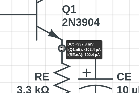
Mouse over element endpoints to see currents flowing into those terminals:
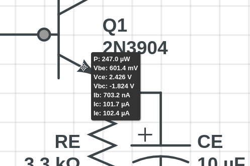
Some circuit elements have custom useful information when you mouse over them. BJTs, for example, will show you the relative terminal voltages like Vbe and Vce, as well as currents Ib, Ic, and Ie:
The new DC Solve Status Indicator at the bottom right of the CircuitLab window lets you know the current state of the Live DC Solver.

The indicator will have one of three states:
The Live DC Solve feature is a powerful tool to quickly probe your circuit and gain insight into what is going on at DC.
Note that this idea only makes sense for steady state DC. If you wish to investigate the transient behavior of your circuit, you still need to think of the conditions you wish to explore, and set those in the Time Domain Simulation tab.
Today we’re launching six new digital combinational gates, now available in your CircuitLab toolbox. These pair well with our recent Quick Toggle feature allowing you to rapidly do digital simulations.
Four new gates are binary adders: a full adder, half adder (no carry input), 4-bit adder, and 8-bit adder:
These can be used for making counters or even an Arithmetic Logic Unit (ALU) of a small CPU.
For example, check out this simulation where we use the 4-bit adder to create a counter which counts up from 0 to 15 before overflowing:
Click to open the circuit above and try the simulation. Can you modify the circuit to increment by 3 instead?
The other two new gates are wider muxes with 4 and 8 data inputs (and 2 and 3 control inputs, respectively):
This allows you to more compactly express higher-bit-width multiplexers without needing to wire up trees of CircuitLab’s old 2x1 muxes.
The new gates are available to all users immediately. This adds to CircuitLab’s existing digital simulation features, bringing us to 5 different types of flip-flops plus 21 different combinational logic gates.
We're excited to announce the release of a new feature that makes exploring digital circuits much easier. Instead of swapping out the digital 1 and digital 0 element in your schematic, the new Quick Toggle feature allows you to switch between a 1 and a 0 digital input by simply highlighting the element and pressing spacebar.
We will likely be bringing similar functionality to other elements to help you quickly explore how changing parts of your circuit affect the behavior.
Circuits with the old digital elements will be automatically updated to the new elements when loaded, so you can simply open up your digital circuits and start designing!
CircuitLab is an in-browser schematic capture and circuit simulation software tool to help you rapidly design and analyze analog and digital electronics systems.