|
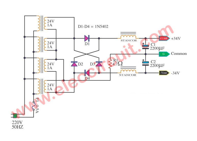
I have made a circuit diagram for a DC power source and is working on building it. However, the voltage and amperage right after the transformer is about 34V, with an amperage spike of about 80A. The amperage then consistently spikes up to about 38A afterwards. Bad power factor to be sure but I'm not at the point where I can build a controller to correct that and our grid should be robust enough to handle a 33V DC power supply. I'm guessing the initial 80 amp spike is due to turning on the supply, but when building the power supply, do I need to get a power transformer that is rated for 80A or more? Or would a transformer rated at ~38A suffice? |
October 12, 2017 |
|
The LM314 is a small regulator, typically up to 1.5 amps. So where is all this current going? I would suggest it is a modelling phenomenon, like charging the smoothing caps from a transformer with zero ohms windings. Try limiting the current with a suitable resistor, about an ohm, added to the model. In real life a transformer of a couple of amps should be adequate for an LM314. You can use average current for power transformers, their thermal characteristics are so slow they won't get hot and melt windings during a half cycle of mains, be it 50Hz (uk) or 60Hz (world). |
")
October 13, 2017 |
|
Looking a bit closer at the circuit, the BR1 symbol represents a bridge rectifier but does not permit setting of all parameters. By using it straight into a 2000 microfarad capacitor you will certainly get high modelled currents, though these won't appear in a real circuit. As I said, try modelling an ohm or two in series between BR1 and C5. |
October 13, 2017 |
|
It definitely reduced the max amperage to about 23A after the transformer, but now I'm curious, how can I get more accurate simulations? Are there other tools I should be using? I understand the best way to learn is to actually build it but I don't want to buy parts on a design that may not even work. |
by brainy19 October 16, 2017 |
|
Perhaps you might permit a little more ripple on C5 by reducing its value? Of course you would have to increase the input voltage. Another way of spreading the current pulse is to have a series inductor like this https://www.eleccircuit.com/wp-content/uploads/2009/11/amplifier-power-supply-using-high-current-transformer.jpg. Sorry I can't supply a value, my best guess is about 1H with a dc current rating equal to your supply output. I would also suggest you use the LM314 with an external pass transistor, as shown in the data sheet, to supply sufficient output current. Power supplies get a bit 'difficult' when you want more than 1A. I would suggest adding protection, at least current limiting and possibly 'fold-back'. |
October 16, 2017 |
|
If you can't get that link, try: https://www.eleccircuit.com/amplifier-power-supply-using-high-current-transformer/ |
October 17, 2017 |
|
...and I said LM314, should've said LM317. |
October 17, 2017 |
|
Awesome, thanks for the input! |
October 17, 2017 |
You must log in or create an account (free!) to answer a question.

Anyone can ask a question.
Did you already search (see above) to see if a similar question has already been answered? If you can't find the answer, you may ask a question.
CircuitLab's Q&A site is a FREE questions and answers forum for electronics and electrical engineering students, hobbyists, and professionals.
We encourage you to use our built-in schematic & simulation software to add more detail to your questions and answers.
Acceptable Questions:
Unacceptable Questions:
Please respect that there are both seasoned experts and total newbies here: please be nice, be constructive, and be specific!
CircuitLab is an in-browser schematic capture and circuit simulation software tool to help you rapidly design and analyze analog and digital electronics systems.