This page describes the major behaviors of the Smart Wires feature.
The smart wires feature is meant to assist the user when editing their schematic by anticipating a user's intentions. When a user selects a particular wire or component to edit, the system also auto-selects certain nearby components that the user might want to edit as well. Components selected in this way are highlighted in blue while the component originally selected by the user remains highlighted in red.
The smart wires feature is available to all premium members of CircuitLab (Hacker Lite plan and up). It is currently not available to users of CircuitLab Free Edition.
To disable the smart wires feature, simply press ALT on the keyboard at any time. All auto-selected elements (highlighted in blue) will become de-selected, and revert back to their original positions.
One of the basic improvements of smart wires is in the behavior of ground connections and named nodes. A ground connected to another element will move together when that part is dragged and moved. The same with a Name Node connected to a particular junction — the Name Node element will be auto-selected by the system when connected elements are selected by the user.
A more powerful feature of smart wires occurs when a component that is connected to a line or another component is dragged and moved by the user. In the majority of cases, with a few exceptions, the system will attempt to maintain the existing connection as the component is dragged around by the user.
Depending on the nearby connected elements, either existing lines will stretch/shrink or new line(s) will be created.
An important exception: no new lines will be created if the selected component is connected along the middle of a line and not at either endpoint. This exception applies if the user selects the component, and not if they select the line (see section Editing Lines).
Selecting a line and dragging it will extend any existing connections it had with other elements. This includes components that are connected along the middle of the line.
Dragging the endpoint of a line will either shorten or extend it, as before, as well as create an optional second wire perpendicular to the first (see section Creating Lines).
Smart wires introduces a slight change in how new lines are created. With the Wire Button selected in the toolbox, clicking and dragging on the canvas will create a new line as before. However, an additional line is now created as well, perpendicular to the first and connected so as to form a L-shaped bend.
The same behavior occurs when extending an existing line by dragging one of its endpoints. This allows the user to quickly connect two components using a L-shaped wire in one action.

Example 1: Ground and Named Nodes are auto-selected in blue
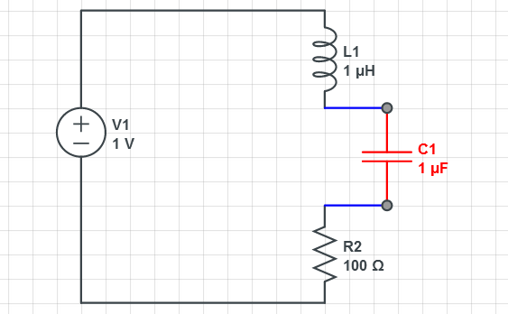
Example 2: Maintaining connections between connected components

Example 3: Creating a new L-shaped wire
CircuitLab is an in-browser schematic capture and circuit simulation software tool to help you rapidly design and analyze analog and digital electronics systems.