CircuitLab is a very flexible tool with a wide range of applications. As with any general purpose user-programmable software, it is possible to get into a broken state where the simulator is unable to find a solution to your circuit, or sometimes to even parse your schematic. Working through these errors requires patience and experience. This guide covers some of the most common issues we see and explains how to solve them.
Before diving into this guide make sure you read our Simulation Basics document as well as the Ultimate Electronics Book section on Schematics and Simulation.
A missing ground node is one of the most common sources of errors. Every circuit needs a ground node to be able to simulate because this defines the circuit’s zero-voltage reference point. When your circuit is missing a ground, you will usually get an "Unable to get solution" error.
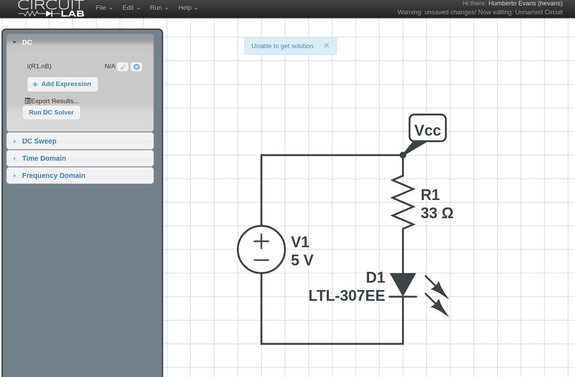
To fix this simply go back to Build mode and add a ground node to your circuit. The ground (GND) element is found at the top of the toolbox under Essentials.

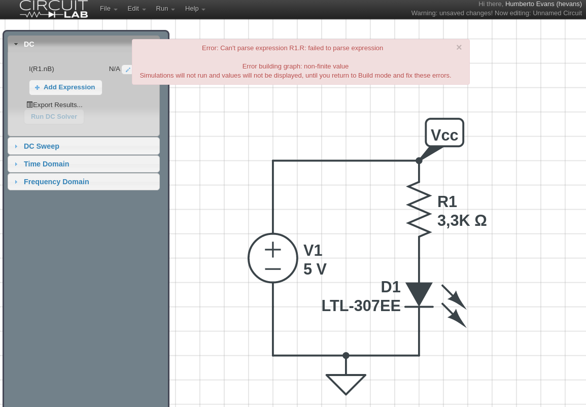
Parameter values in CircuitLab are extremely versatile, but the versatility can be a double-edged sword. A common error case is a parameter that cannot be parsed by the engine. In this example, a simple typo attempting to type 3.3K into the resistance parameter, resulted in 3,3K with a comma instead of a period. CircuitLab's expression parser is unable to figure out what this means and triggers an error when switching to Simulate mode.
Here is another example of a similar error. In this case the user typed "x" into the resistance value. There are some situations in which this is a valid use case, however here the parameter x is not defined anywhere else which causes CircuitLab to throw an error.
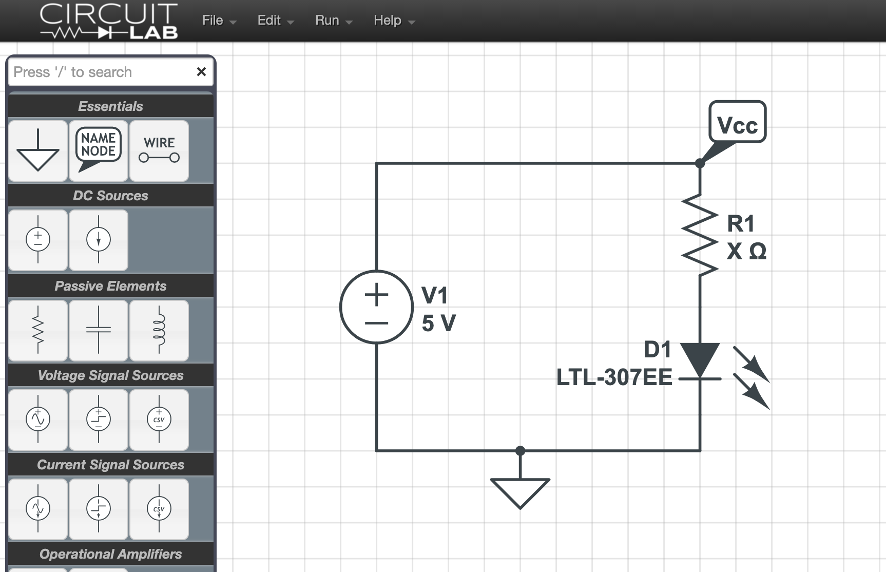
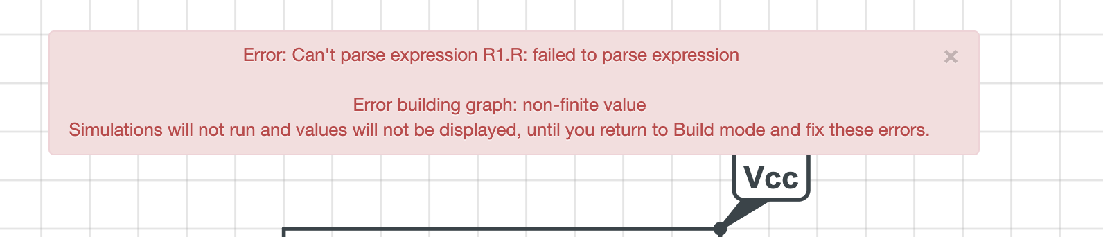
To fix this issue, go back to Build mode and double check all your parameter values in your circuit. Make sure they are all numbers, or expressions that can evaluate correctly. In some situations CircuitLab is able to tell you roughly where the error is. In the error shown below it is telling us the parameter R1.R has an issue.
Note that parameters in CircuitLab can be used to build arbitrarily complex expressions. See for example the Behavioral Sources section in CircuitLab Academy. Tracking down the source of the issue can be tricky, so be patient and methodical.
When dropping new components into your schematic, CircuitLab ensures that the new elements all have a unique name. However, when you are recreating a schematic from another source like a book or problem set, it is natural to rename the components to match the reference. This can sometimes result in a “Duplicate component name” error message when simulating if the names of the elements are not all unique.
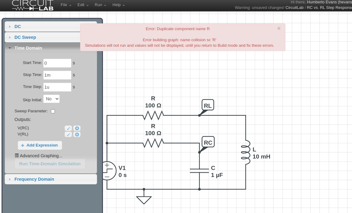
In this case, CircuitLab is usually able to let you know which elements have a duplicate name. To fix the issue, simply go back to Build mode and change the names of the two resistors to R1 and R2 to make them unique.
Unconnected elements will often cause a simulation to fail because the simulation engine is unable to assign currents or voltages to the unconnected nodes. This can often happen when you are drawing your circuit and you pan around and forget about an item you dropped. In the example below it’s very easy for R4 to be hiding behind the toolbox or off the edge of the viewport.

To fix this, try zooming out to make sure you don't have any stray components. You can also click Edit -> Zoom To Fit which will put all your components in the current viewport. In very busy schematics with lots of elements, unconnected components can hide in plain sight, so look closely at your circuit.
Two components directly on top of each other can sometimes create a situation where the simulator is unable to find a solution to the circuit. In the example below there are actually two voltage step sources on top of each other. This can happen if you accidentally drag more than one component from the toolbox, or if you use copy and paste on an element and don't move the new element out of the way.
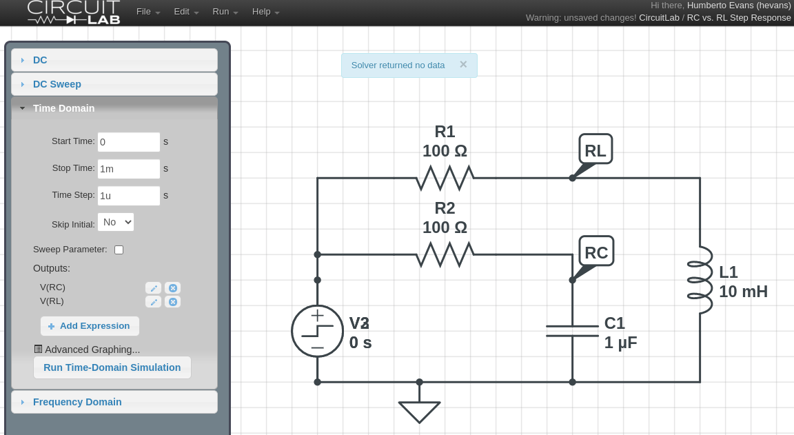
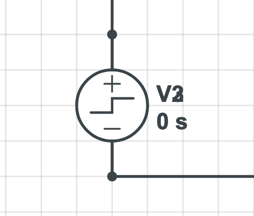
You can find duplicate elements by looking closely at the element names where you will notice the V2 is hiding a V3 behind it.
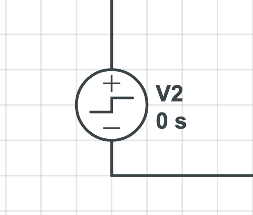
The other telltale sign is the connection dots at the terminals of the step source V2. CircuitLab will draw a connection dot anywhere more than two terminals meet. In this case the terminals of the wire meeting V2 should not show a connection dot, however the hidden V3 makes a third terminal and causes the dot to show.
If you’ve checked for all the issues above and still can’t get your circuit to simulate, please:
For more resources on using CircuitLab take a look at:
CircuitLab is an in-browser schematic capture and circuit simulation software tool to help you rapidly design and analyze analog and digital electronics systems.