Welcome to CircuitLab Academy! Learn our most popular keyboard and mouse shortcuts. Follow the screenshots below to draw a circuit and get simulation results quickly.
Click and drag components from the toolbox onto your schematic:

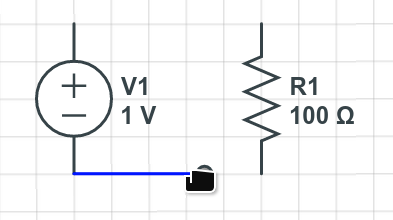
Simply click and drag from component terminals to extend wires to connect your components:
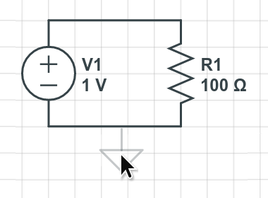
Press G to insert a ground node, and click to place it:
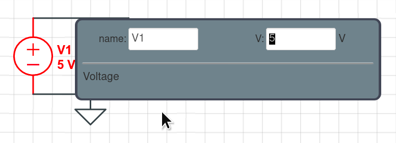
Double-click a component to change its parameters. Let's make V1 be 5 volts:
Click to select V1 and press H to flip the symbol horizontally, so the text is drawn on the other side:

You may also use V to flip vertically, as well as R and Shift+R to rotate.
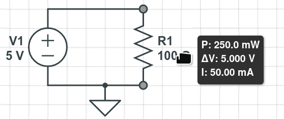
Mouse over a component to see it’s DC simulation results, such as the power dissipation, voltage drop, and current through resistor R1:
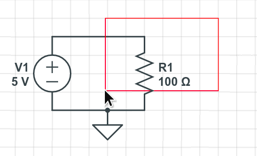
Drag on the grid to select R1 and then press Backspace or Delete to remove it from the schematic:
Press / (forward slash) to begin a toolbox search and enter "100k" in the search box:
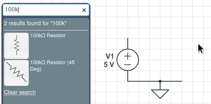
Click and drag the 100k-Ohm resistor from the toolbox to your schematic:

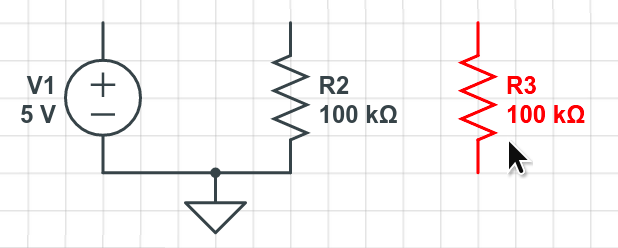
While this new resistor is selected, press Ctrl+C to copy R2, then Ctrl+V to paste. Click and drag this new resistor R3 off to the side:
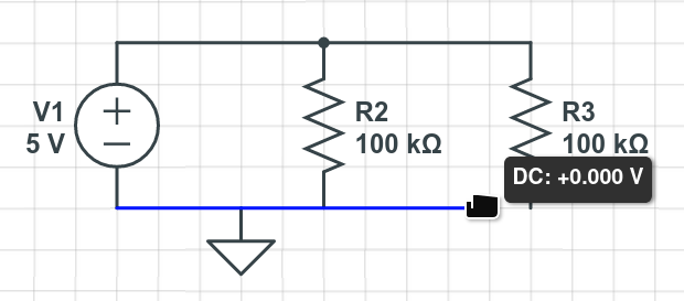
Click and drag to extend wires so that R2 and R3 are in parallel and connected to V1:
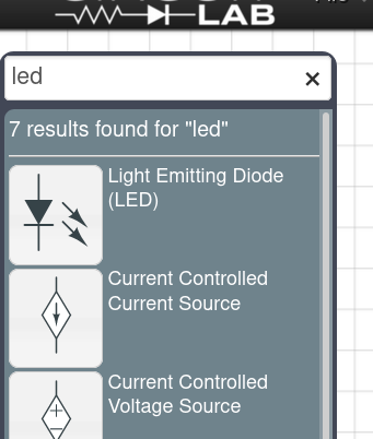
Press / (forward slash) to begin a toolbox search and type "LED":
Click and drag the Light Emitting Diode from the toolbox. While still dragging with the mouse, press Shift+R to rotate it counterclockwise, and release it on the wire segment joining R2 and R3:
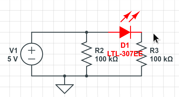
Notice that the diode D1 has replaced the wire segment it was dropped on top of.
Our labels are overlapping, so let's click and drag on wires and components to give them some breathing room:
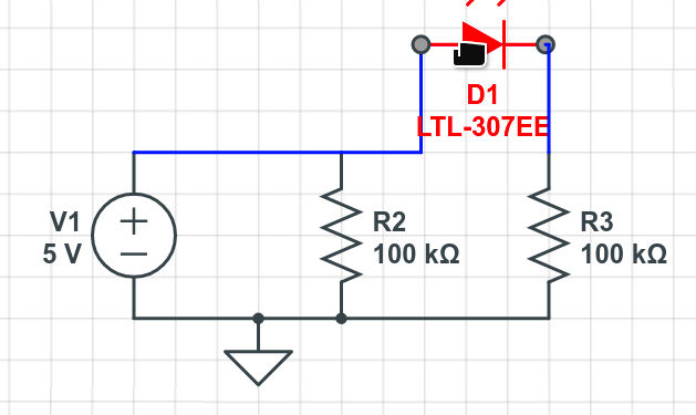
Notice that CircuitLab's Smart Wires feature tries to keep your circuit connected as you drag a wire to rearrange components:

If you don't like what the Smart Wires feature is doing, just press Esc while you're dragging and your selected components will be allowed to disconnect.
Part of the circuit is now hidden by the menu bar. Use the mousewheel to zoom. To pan, drag with the middle mouse button, or hold Ctrl while dragging:

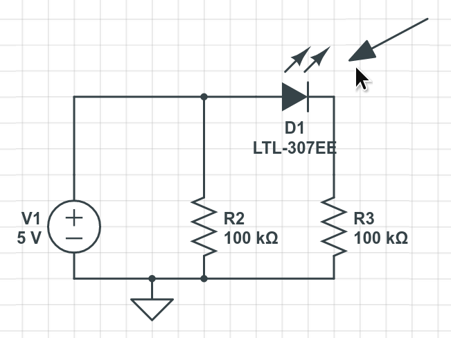
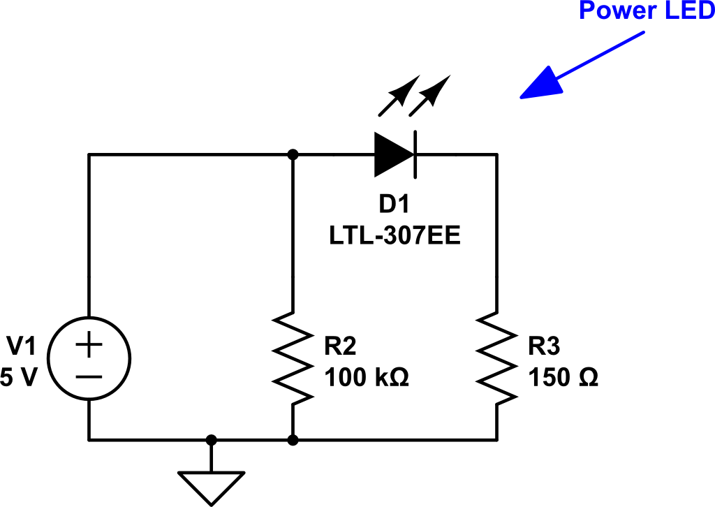
Press A to draw an arrow, first clicking at the arrow's tail and dragging to the arrow's head:
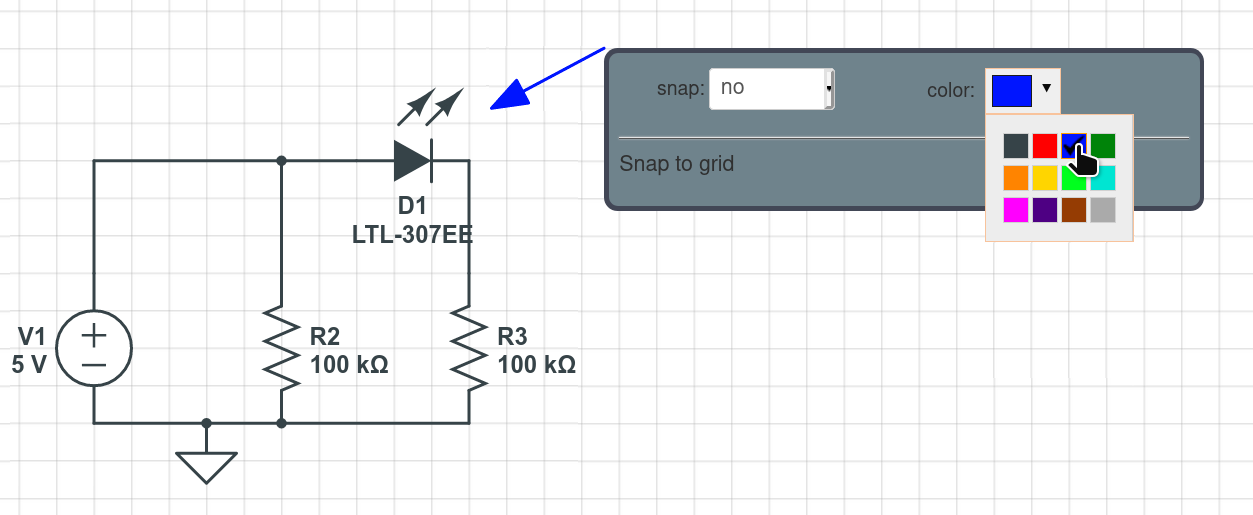
Double-click the arrow and change its color to blue:
Press T to add a text element, and click to place it near the arrow's tail:

Double-click the text element and make it blue with the text "Power LED":

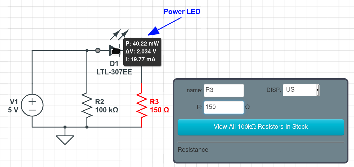
Double-click resistor R3 and change its resistance until you have a current of about 20 mA flowing through the LED, hovering your mouse over D1 to check as you go:
Press Ctrl+S to save your circuit:

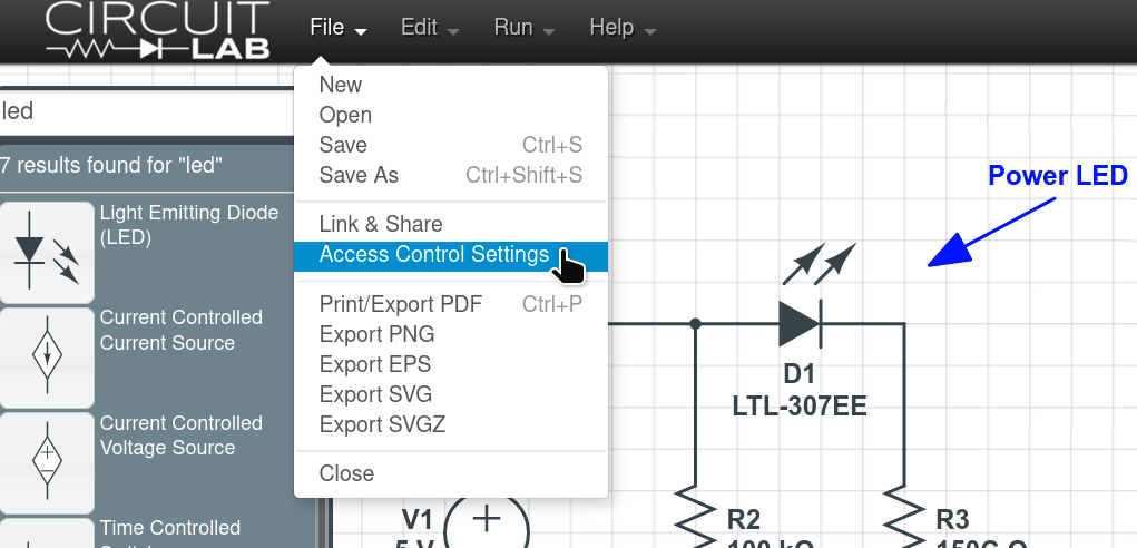
Open the File menu and change Access Control Settings to make your circuit public, or export a PDF, PNG, or other image type:
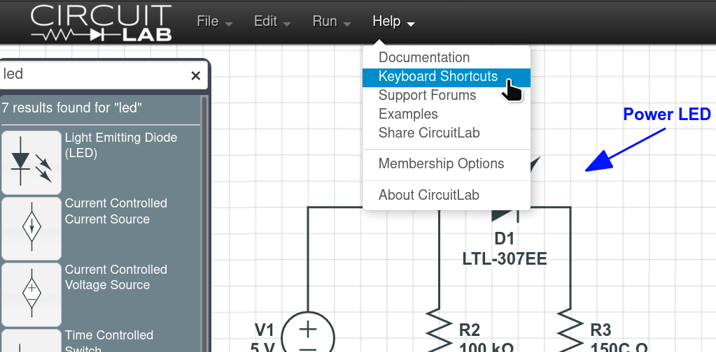
Open the Help menu to see more resources like our documentation and community support forums:
That's enough to get you started drawing circuits and simulating productively!
Click below to open the final circuit, or try it yourself from scratch (recommended).
CircuitLab is an in-browser schematic capture and circuit simulation software tool to help you rapidly design and analyze analog and digital electronics systems.