|
I want to make a button which control both ac and dc light When button is on If there is Electricity Then AC bulb will be on Else DC bulb will be on And if button is off both ac ane dc bulbs should be off AC bulb upto 25 watt Dc bulb upto 20 watt |
August 18, 2020 |
|
What is the voltage (average over half a cycle and frequency) for the AC voltage? Ex.: 120 volt, 60 Hz ( for 170 volt max, or 340 volt peak to peak ). |
August 18, 2020 |
|
Ac 230 v 50 hz |
August 18, 2020 |
|
Just in case you're trying to make what i think you're trying to make... Please do not use any DIY solution to build a mains voltage tester that you intend to use on a live circuit. Apologies if i misread your intentions. |
August 19, 2020 |
|
It would be useful to know somewhat more about the devices that you want to control in order to possibly help. Are the two bulbs in completely separate fixtures? Or, are they in the same fixture/device, and possibly the DC bulb acts to back up the AC bulb in the event of a mains power loss. Similar to a lighted EXIT sign which normally runs from the mains, but is backed and lighted up by a DC source in the event of AC power loss. You specified that the AC is 230V 50 Hz; what is the DC source (battery?) voltage? As much detail as you can provide would certainly help. Then, it may be possible to design a solution, but the designer would need to understand all of the elements and relationships involved to craft a safe design. As previous comments have indicated, mains voltages, 115 or 230, are not something to be casual about. |
by jaf2009 September 02, 2020 |
|
Dc 12v 12w led light Actually i want to control two bulb ac and dc from one button If button is on and there is wapda it should on Ac bulb other wise dc if wapda com back sc should be on If button is off then both ac and dc should be off |
September 11, 2020 |
|
If I understand correctly, you want to control both lights as follows: The 230VAC Bulb is on when Mains power is present, and the 12VDC Bulb comes on when Mains power is lost. Moreover, you want to control turning on/off both lamps with one switch. Please see my circuit: https://www.circuitlab.com/circuit/j8bu8xbaejcj/ac-dcbulb-solution/ |
September 13, 2020 |
|
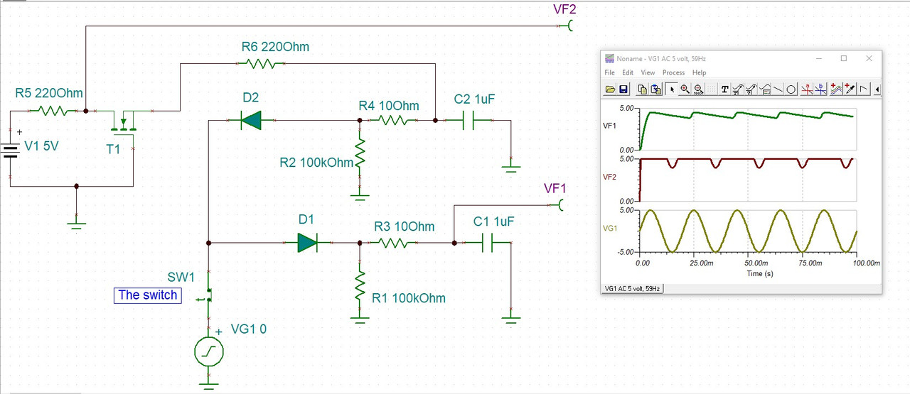
I haven't been able to run a time domain simulation, here, but it seems to be working. First, I don't know what is a "wapda". I assumed that the goal was to possibly determine if a source, here V1, is an AC or a DC, while the circuit has to be not-mobile, stationary. I also assumed that you can decrease the possible AC voltage to around 5 volt (peak to algebraic mean of zero volt). The circuit principle is quite simple, a diode allow a capacitor to be charge, when the voltage is on the appropriate "direction". For a DC voltage, that occurs just for one of the two groups Diode-capacitor, while for an AC voltage, that allows to charge the two capacitors. I haven't show the switch, but it could be between at one of the two terminal of the source V1. The capacitors R1 and R2 would automatically bleed the capacitors to 0 volt when you turn the switch off. You can increase their value to minimize the power consumption of those, then the switch is on. The two op-amps are used to buffer the voltage at the end of the capacitors. The and-gate will turn on if both op-amps supply a voltage as a logical high. The op-amps and the logic circuit used should be compatible, including the fact that most op-amps CANNOT reach the rail voltage, here, they cannot REACH 0 volt exactly (but probably something around 1 volt as the minimum output that they can reach, as a minimum output). Have a logic circuit family which will consider that low voltage as being a logical 0. The XOR (or XNOR) gate produces a high value if one and only one of the two op-amps generates a logical high, that is, if the source V1 is DC. Here, the two bulbs are represented with LED, but if you are using 12V bulbs, the logic circuit (AND and XOR gates) would probably not be able to supply that. You will need to add transistors or relays (which is relatively a standard circuit that I didn't found required to be shown here). And once again, working with high voltage (that is, more than 50 volt) can be life threatening, or can cause serious damage or be the reason for a fire. |
by vanderghast September 12, 2020 |
|
This is an improved circuit: The switch is shown, the capacitors properly discharge when the switch is turned off, and the op-amps are removed. Connect VF1 and VF2 to the AND gate and to the XOR gate. The small circuit at the top left is to change the -5 volt from the AV source ( with 5 volt amplitude) to +5 volt. You can use a different sub-circuit to your liking for that part. |
September 13, 2020 |
You must log in or create an account (free!) to answer a question.

Anyone can ask a question.
Did you already search (see above) to see if a similar question has already been answered? If you can't find the answer, you may ask a question.
CircuitLab's Q&A site is a FREE questions and answers forum for electronics and electrical engineering students, hobbyists, and professionals.
We encourage you to use our built-in schematic & simulation software to add more detail to your questions and answers.
Acceptable Questions:
Unacceptable Questions:
Please respect that there are both seasoned experts and total newbies here: please be nice, be constructive, and be specific!
CircuitLab is an in-browser schematic capture and circuit simulation software tool to help you rapidly design and analyze analog and digital electronics systems.